Comparing ray tracing results with approximation formula
Warning: Firefox renders the formulas
correctly (Chrome and Microsoft
Edge can't properly render the formula [MathM] correctly)!!!
The refraction approximation formula are quite known and coming
from the astronomy, navigation and geodesy environments and are
mentioned in this link. These
approximation formula are (all result in [deg] or [m]):
- astronomical refraction
- Sinclair (Bennett [1982,
page 257], formula B at NearHeight=0m, 10°C and 1010mbar)
- levelling
refraction (dip due vast level surface)
- based on Young (Young, 2003 at 15°C and 1013.25mbar),
- Nautical Almanac (2017)
- Distance to horizon:
Lray (Young, 2003 and adjusted to map US1976:
changed 3830 to 3910)
- terrestrial
refraction
- based on Thom (Thom, 1973, page 31, (3.6) at 15°C and
1013.25mbar)
Legend
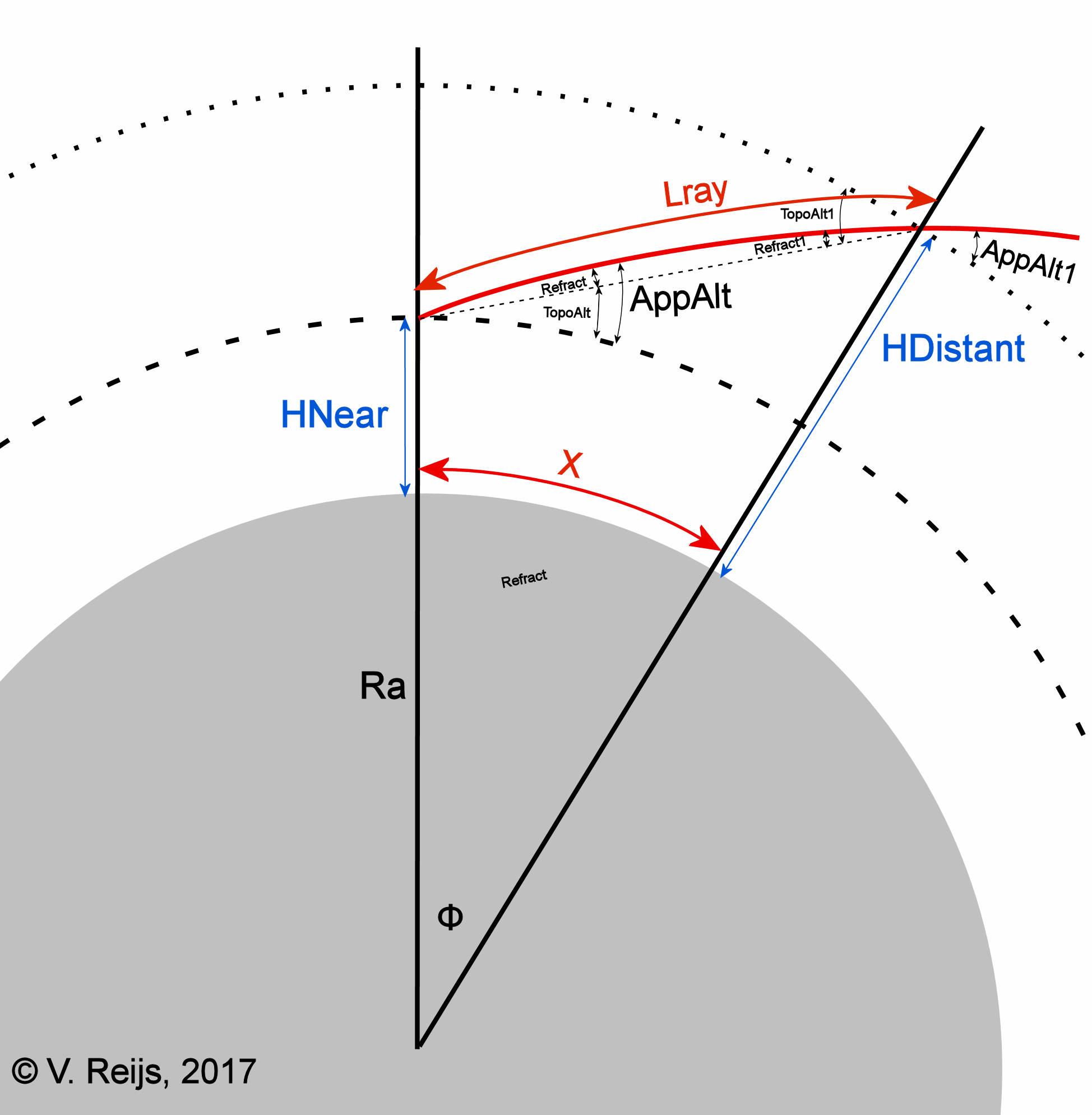
DistantHeight: Elevation of the target [m]
NearHeight: Elevation of the observer [m]
K: average Refraction Constant [-] = (0.0342
- Lapse rate) *272.84 and K=k/0.0238
Lapse
rate: Average lapse rate [K/m] (remember 'Lapse rate' is the
negative of 'Temperature gradient')
P: Pressure at NearHeight [mbar]
T: Temperature at NearHeight [°C]
Ra: Radius of Earth [m]
Lray (or S): Length of the light ray [m]
X: Distance along Earth's geoid [m]
AppAlt: Apparent altitude at NearHeight [°] (AppAlt=TopoAlt+Refract)
The above approximation formula are
compared with the results of the ray tracing implementation from
Reijs: RefractHOSI, which based on integration
along apparent altitude (Hohenkerk&Sinclair, 1985). Benchmarking astronomical and
levelling refraction showed that the refraction variation in
results was max. 2" (around 0.05%): with integration along
apparent altitude (pers. comm, Tschudin, Young, 2017) and with
integration along Earth's geoid (pers. comm. van der Werf, 2017).
Benchmarking terrestrial refraction was successfully spot checked
with van der Werf's implementation which uses integration along
the Earth's geoid (pers. comm, van der Werf, 2017).
Here are the different refraction comparisons (at 1 arcmin
level, aka ~1/30 of diameter of Sun/Moon), so that we can
determine the validity of the approximation functions coming from
the astronomy, navigation and geodesy environments:
- Astronomical refraction
The refraction is determined for a light path from the eyes'
position to the end of the Earth's atmosphere (in direction of a
celestial object).
- Levelling
refraction
The refraction is determined for a light path that has a
large part level with the Earth's geoid, aka towards a vast
level surface below the eyes' position. Also known as dip.
- Terrestrial refraction
The refraction is determined for a light path that goes from
the eyes' position to a terrestrial object higher or lower than
the eyes' position.
Astronomical refraction
Under the condition of Standard Atmosphere (US1976, T0=15°C
and P0=1013.25mbar, λ=600nm, Rearth=6378120km),
the below picture provides comparison between AstroRefractHOSI
and AstroRefractATS (formula 1):
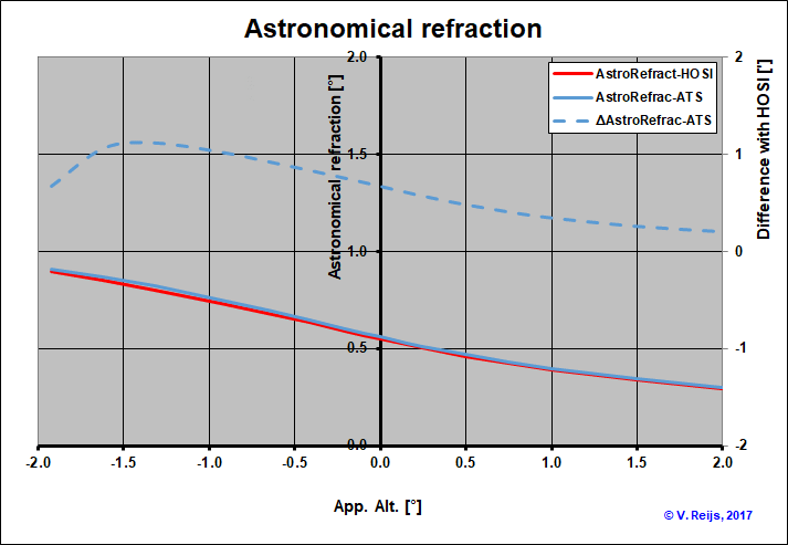
The difference between the two is max. 1.2' (blue dashed line and
the right axis). This small difference is expected as Sinclair
(1978) was part of the implementors of the Hohenkerk&Sincliar
(1985) program (although his published formula looks to be earlier
than the publish computer program).
Levelling
refraction (dip due to vast level surface)
Under the condition of Standard Atmosphere (US1976, T0=15°C
and P0=1013.25mbar, λ=600nm, Rearth=6378120km),
the below picture provides comparison between LevelRefractHOSI,
LevelRefractVR (formula 2) and
LevelRefractNA (formula 3):
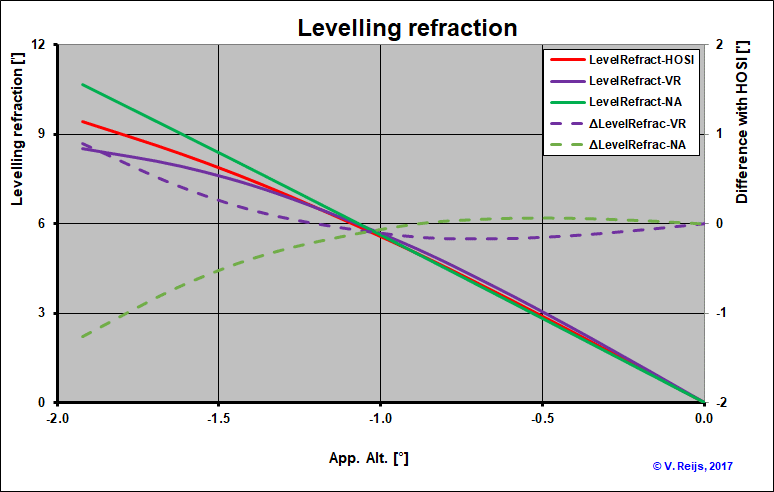
The difference between LevelRefractHOSI and LevelRefractVR
is max. 1' (purple dashed line and the right axis) and LevelRefractNA
is max. 1.2' (green dashed line and the right axis). They are not
that far from each others (certainly below a height of 2000m,
equivalent to AppAlt=-1.3°), which is expected as all are used for
Standard Atmosphere (US1976) environments.
Average lapse rate or detailed height-temperature profile?
Andrew Young states: "George Kattawar and I [Andrew
Young] showed that the dip depends almost entirely on the
difference in temperature between the air at eye level and that at
the apparent horizon, regardless of the thermal structure in
between.".
Beside the temperature difference (average temperature
gradient), the temperature/pressure at one of the points is
important (as that also changes the refraction). So a high
resolution height-temperature profile is not that important in these
dip/levelling cases.
This has been tested by using two
different height-temperature profiles:
- The temperature starts at 15°C and stays constant up to half
eye-height, and then the temperature changes gradual to
eye-height. The temperature at eye-height is determined by the
average lapse rate defined for each 'experiment'.
- The temperature starts at 15°C and change gradual up to half
eye-height and then it stays constant up to eye-height. The
temperature at eye-height is determined by the average lapse
rate defined for each 'experiment'.
Example: if average lapse rate is 0.0065K/m and the ground
temperature is 15°C, the temperature at eye height (3000m) will be
-4.5°C (=15-0.0065*3000). The slanted profile (on left
side) has twice the average lapse rate (0.013K/m) up to half
eye-height (1500m) and then the lapse rate is zero up to eye-height
(3000m), while in the perpen[dicular] profile (on the right
side) the temperature stays at 15°C up to half eye-height (1500m)
and then it changes with twice the lapse rate (0.013K/m) up to the
eye-height (3000m):
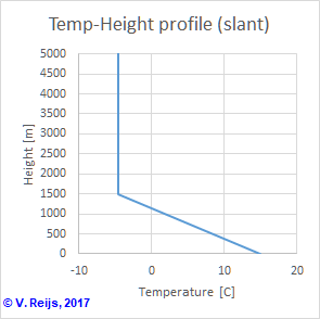
Slanted temperature change
(eye-height=3000m)
|
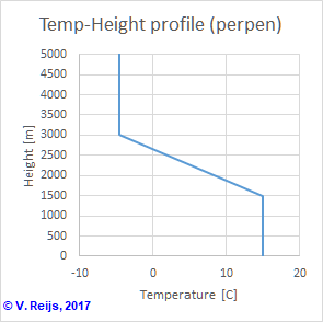
Perpendicular temperature change
(eye-height=3000m)
|
The temperature gradients near the horizon are thus considerable
different for the two height-temperature profiles: 0.013 (slant)
and 0 (perpen) K/m.
If we use these different height-temperature
profiles (slant and perpen) for an average lapse
rate of -0.01, 0.0065 and 0.02K/m the below picture emerges. The
LevelRefractHOSI (continuous lines) and LevelRefractVR
(dashed lines) have been calculated:
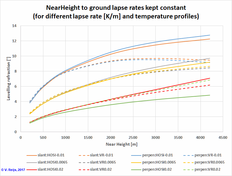
For the cases of average lapse rate 0.0065 and 0.02K/m the
LevelRefractHOSI (continuous lines) and LevelRefractVR
(dashed lines) are comparable. This is not the case for average
lapse rate -0.01K/m. For some reason they diverge for higher Near
Heights (>1000m). A possible reason could be because the
approximation formula 2 is valid for small angles
and low heights. Heights of up to 4200m were chosen because of the apparent altitude measurements
of the sea level (due to dip aka levelling refraction) by
Schaefer&Liller (1990).
The two different height-temperature profiles (slant and perpen)
don't really produce large differences (except perhaps slightly
larger differences for the average lapse rate 0.02K/m). So Andrew Young's statement looks to be correct.
Terrestrial refraction
Under the condition of Standard Atmosphere (Rearth=6378120km,
T0=15°C and P0=1013.25mbar), the terrestrial
refraction per kilometer depends on average lapse rate (remember
'Lapse rate' is the negative of 'Temperature gradient') as seen for
the formula 5 and formula 6
below:
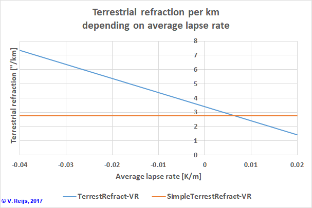
Lapse rates of -0.04 (Stability
Class=G: likely around midnight) to 0.02 (Stability Class=A: likely
around noon) K/m maps Refraction Coefficients (K) of ~20 to ~4
[-]. And these are numbers that are also found through Thom's
observations. The two curves cross at a lapse rate of
0.0065K/m (which is expected as the simple approximation (formula 6) is derived for 0.0065K/m only).
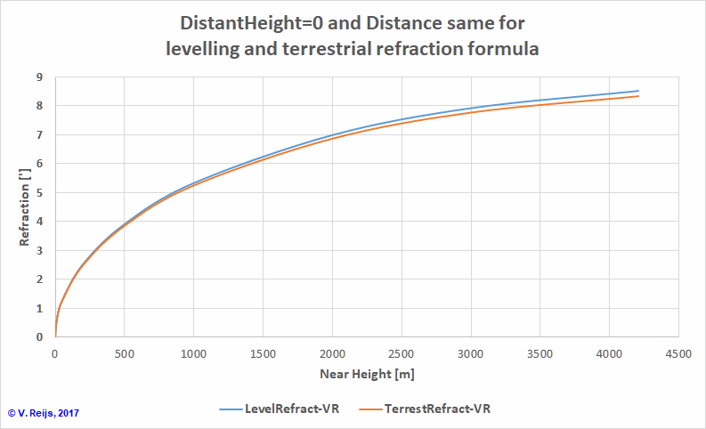
Under the condition of Standard Atmosphere (US1976, Rearth=6378120km,
T0=15°C and P0=1013.25mbar), levelling
refraction (formula 3) and terrestrial refraction (formula 5) should come to the same results if the
Distance for terrestrial refraction (in formula 5: Lray)
is made the same as the level distance to horizon (formula
4) and having the same height differences. In the below figure
one can see that the results are similar (within 0.2'):
To determine TerrestRefractHOSI a slight addition is
needed to the ray tracing procedure. The terrestrial refraction has
three parameters: HNear, HDistant and
Distance (over Earth's geoid). The Distance (X over Earth's geoid)
can be easily determined by changing Hohenkerk&Sinclair
procedure to calculate the distance integral instead of the
refraction integral (van der Werf, 2008, Table 1, column 2). The
Apparent Altitude at the HNear is varied (in an iterative
way) so that the light ray at Distance X goes through HDistant.
Under the condition of Standard
Atmosphere (US1976, T0=15°C and P0=1013.25mbar,
λ=600nm, Rearth=6378120km), comparing the TerrestRefractHOSI
(blue line) and TerrestRefractVR (red line) shows that
below HDistant=1000m the two have similar behavior:

It might be that the TerrestRefractVR (formula
5) is too much an approximation.
Using the same
two height-temperature profiles as for levelling refraction (slant
and perpen) for an average lapse rate of -0.01,
0.0065 and 0.02K/m, the below picture emerges for terrestrial
refraction. The TerrestRefractHOSI (continuous lines) and
TerrestRefractVR (dashed lines) have been calculated:
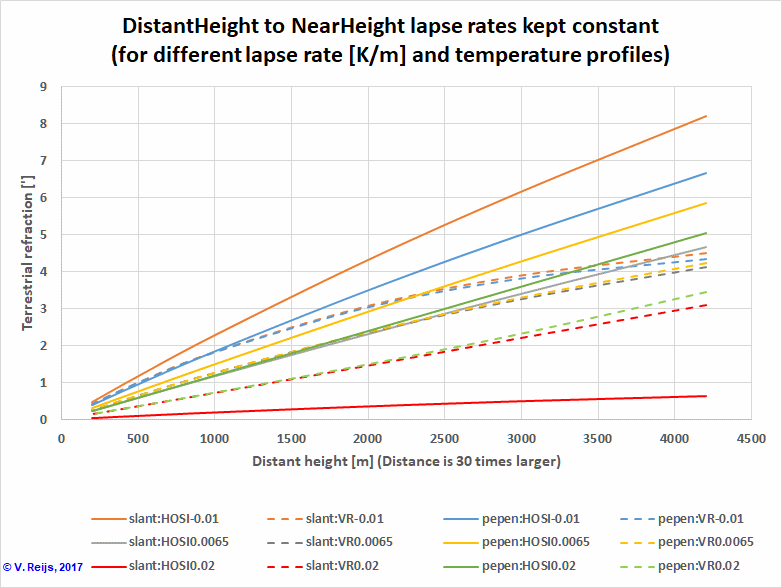
The comparison for 0.02K/m is quite difficult as TerrestRefractHOSI
(green and red continuous lines) and TerrestRefractVR
(green and red dashed lines) are quite diverse, reason unknown yet.
The others two lapse rates (-0.01 and 0.065K/m) are closer up to HDistant=1000m.
There might be a possibility that the approximation formula
5 is not accurate enough, so need to check that.
Conclusions
Common to all types of approximation refraction formula: below HDistant=1000m
the approximation formula and the ray tracing method give similar
results, while with an average lapse rate of 0.0065K the mapping is
best say up to HDistant=2000m . This looks to be inherent
to these approximation formula.
No direct evaluation has been done on changing the T0 and
P0 at HNear: up to now the US1976 conditions
and some specific height-temperature profiles (slant and perpen)
were used, but the ray tracing function can use any T0, P0,
and height-temperature profile.
At this moment, I am not planning to determine new/other formula; as
ray tracing is nowadays a simple and valid method to determine the
refraction in a unified way, as was recognised
in the past.
References
Bennett, G.G. 1982. 'The calculation of astronomical refraction in
marine navigation', Journal of Inst. navigation, Vol 35: pp. 255-59.
Hohenkerk, Catherine Y., and A.T. Sinclair. 1985. "The computation
of angular atmospheric refraction at large zenith angles." ed. by HM
nautical almanac office. Cambridge.
Reijs, Victor M.M. 2007.'Refraction: Refraction calculation', in
http://www.archaeocosmology.org/eng/refract.htm#Calculated [accessed
2 July 2012].
Schaefer, Brad E., and William Liller. 1990. 'Refraction near the
horizon', Publications of the Astronomical Society of the Pacific,
Vol 102: pp. 796-805.
Sinclair, A.T. 1978. "Data for astro-navigation in 1978 for use with
small calculators." ed. by HM nautical almanac office. Cambridge.
Thom, Alexander. 1971. Megalithic lunar observatories (Oxford
University Press)
Werf, Siebren Y. van der. 2003. 'Ray tracing and refraction in the
modified US1976 atmosphere', Applied optics, Vol 42: pp. 354-66.
Werf, Siebren Y. van der. 2008. 'Comment on “Improved ray tracing
air mass numbers model”', Applied optics, Vol 47: pp. 153-56.
Acknowledgements
I would like to thank people, such as Siebren van
der Werf and others for their help and constructive feedback. Any
remaining errors in methodology or results are my responsibility
of course!!! If you want to provide constructive feedback, let me know.
Disclaimer and Copyright
 Home
Home Up
Up Search
 Mail
Mail
Major content related changes: December 1, 2017


