NEW
This web page will look into measurements of an G5RV junior antenna. The following sections are covered:
<puple text needs to be further
investigated: conflicted or unknown results/thoughts>
This webpage provides an overview of the experience gained by
building, measuring and simulating a G5RV junior antenna.
| Term |
Description |
| Dip frequency |
The frequency [MHz] where the SWR dips. Be aware that the Dip frequencies depend if measured (using NanoVNA) or simulated (using MMANA-GAL or NEC-2 for MMANA) |
| Dip wavelength |
The wavelength [m] of the Dip frequency
(300/Dip frequency). |
| Band range |
The min, mid and max frequencies [MHz] in an
amateur band [m] |
Original article of Louis Varney [1958]: https://www.qrpforum.de/index.php?attachment/20212-g5rv-org-pdf/
Updated article by Louis Varney [1984] on full (and a tille about
the junior) G5RV: https://midsussexars.org.uk/downloads/g5rv_multiband_antenna.pdf
Some information about Louis Varney and his full G5RV: https://www.youtube.com/watch?v=I28XUmbUXsA
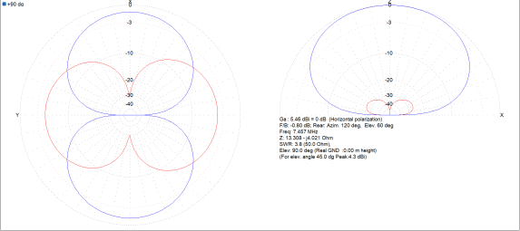
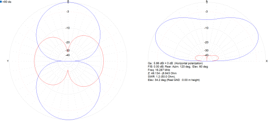
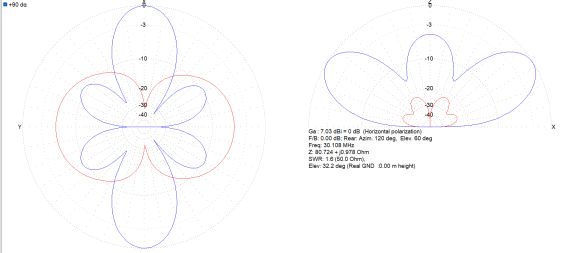
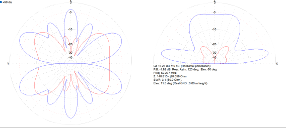
So looking at a G5RV junior antenna (which compares in some way
with the general description of the full G5RV [1983]). The Dip
frequencies, standing wave [on half-dipole and ladder) and polar
diagrams are (illustratively) from MMANA-GAL simulations.
<if looking at full G5RV in MMANA-GAL, we see the similar
standing wave and polar diagrams, but than for a twice lower
frequency.
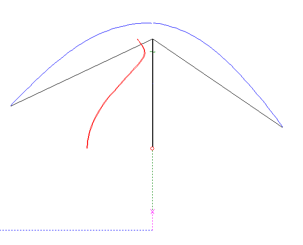
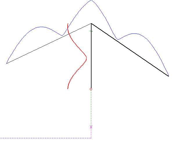
The standing wave diagrams for 3.5 and
7Mhz look slightly different in Varney's article [1984];
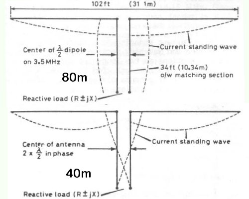
The reason could be that Varney [1984]
used the Band range frequencymin, while below the Dip frequency was used).
Folding back the shortened half-dipoles: https://amateurradiotechsupport.freshdesk.com/support/solutions/articles/51000082880-g5rv-multi-band-antenna
Shortening my G5RV on both half-dipoles from a 25cm folded back to
(by clipping it away) a 12cm folded back; No significant
difference.
http://hyperphysics.phy-astr.gsu.edu/hbase/Tables/diel.html
Polyethylene (PE) insulation is being used for ladder and dipole:
~2.25
Determine VF of wire: https://groups.io/g/nanovna-users/topic/velocity_factor_measurement/106153112?page=3
VF for 450Ω PE ladder 0.902: https://www.ebay.com/itm/314582526493
VF insulated dipole wire (PE Koper/RVS Litze) has according https://lowpowerlab.com/guide/rf-best-practices/velocity-factor/
an additional factor of 0.95 –
0.98 (for PVC, Polyethylene, Teflon) beside the VF=0.95 for a
bare wire. So the resulting VF would between 0.90 and 0.93 for
insoluaed wire.
By using a dipole simulation in NEC-2 for MMANA, an
VF=0.95 was gained.
Someone though explicitly tested this insulated wire and got an
VF=0.94 [pers. comm. HF kits, 2025].
| Amateur band |
fbandmin |
fbandmid |
fbandmax |
| [m] |
[MHz] |
||
| 40 |
7 |
7.1 |
7.2 |
| 20 |
14 |
14.175 |
14.35 |
| 10 |
28 |
28.65 |
29.3 |
| 6 |
50 |
51 |
52 |
G5RV junior implementation guidelines: https://www.hfkits.com/instructions-zs6bkw-g5rv-junior-mini-includes-11-balun/
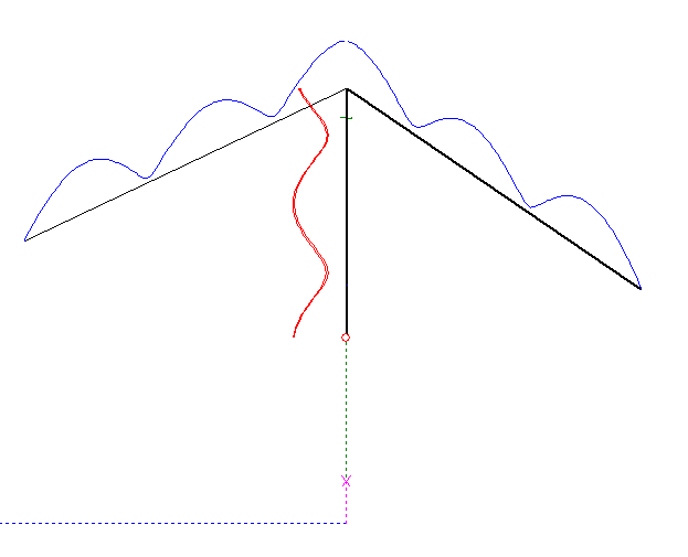
Inverted V (see here for the general layout): top height 9m and the half-dipoles ends go down to around 4.8m and 5.8m (angle between the half-dipoles some 120deg).
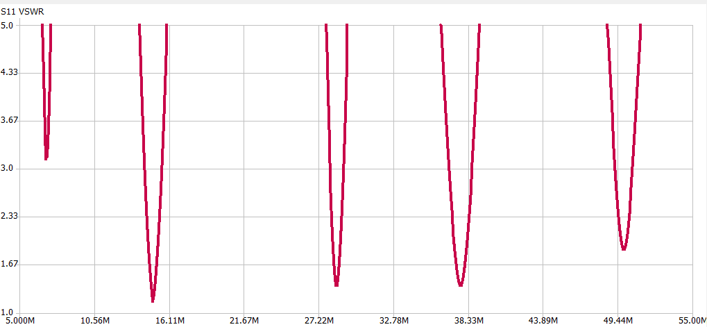
The Dip wavelengths are determined using NanoVNA
and NanoVNASaver.
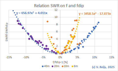
If we determine a ratio of length of half-dipole plus ladder
divided by λ(dip)/2; this should be constant
for each bands and half-dipole or ladder lengths:

The following have been m(easured) and
s(imulated):
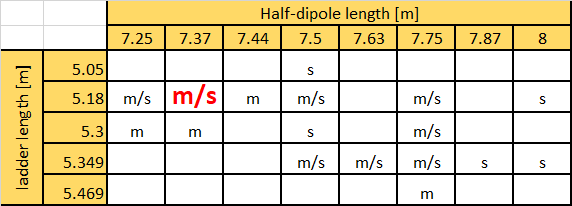
In below figure the half-dipole length is varied between 7.25 and
7.37m and the ladder length between 5.18 and 5.3m:

The above red coloured cell (half-dipole length: 7.37m and ladder length:
5.18m) looks to be the optimum for my
setup.
A slightly different G5VR setup (lower inverted V: top at 7m and
the half-dipoles ends at 3m) had the optimum half-dipole length at
7.25m and ladder length at 5.3m [pers.comm. HF kits,
2025]. So not that far off from my own experience.

The VNA measurements of the G5RV antenna are compared with the
readings of the ATU-100 EXT device. This is done by using the Smith chart.
Nichols, Steve: An introduction to antenna modelling. Bedford,
Radio Society of Great Britain 2014.
Varney, Louis: An effective multi-band aerial of simple
construction. In: RSGB Bulletin July (1958), pp. 19-20.
Varney, Louis: The G5RV multiband antenna ... Up-to-date. In:
Radio Communications July (1984), pp. 572-575.