Two type of sides are
important:
- the camera side
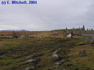
- cam1 will be in waterproof container. Located near old post office facing south horizon (Sleeping Beauty + Calanais I). FoV~74°
- cam2 will be in waterproof container. Located on Blackhouse Tearoom roof facing north-west horizon of Calanais I. FoV~11°
- the PC side
- PC1 for cam1 and
cam2 has a Winnov Videum ISA card (cam1
will use RCA tulip connector and
cam2 will use MXC connector). Located in Blackhouse Tearoom.
I think the Win98 systems is stable enough as long as an ethernet connection can be used for Internet connectivity (and not dialup). Installing this Winnov Videum ISA card can be problematic (not really plug-and-play), so help can be provided (in some cases you need software to fix registry, see link of software download page).
Be sure to configure all video inputs as PAL (and not NTSC).
- PC1 for cam1 and
cam2 has a Winnov Videum ISA card (cam1
will use RCA tulip connector and
cam2 will use MXC connector). Located in Blackhouse Tearoom.
- the camera side
- cam1
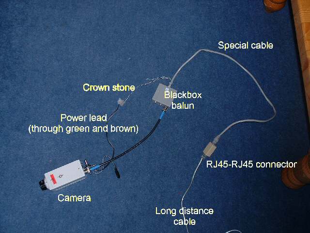
A short explanation of this buildup:
- long distance cable
This cable goes between the cam1 and PC1 locations (upto 600 meter). This cable (RJ45 Cat5 UTP, ethernet cable) is used to transport the video signal and the power to the cam1. Only a short ethernet cable is provided by me. - RJ45-RJ45 coupler
The connector connects the long distance cable to the special cable - Special cable
This cable splits the video signal and the power. The video signal ends up in the RJ45 connector (to the Blackbox balun), while the power goes to the two twisted pairs into a crown stone - Crown
stone
This connects to the power lead towards the cam1. This power lead is clipped from the power supply (be sure that the plus and minus are connected to resp. brown and green lead, if in doubt phone me, it can damage the camera!); at the other end is the 12V DC power plug (1.2 mm x 5.5 mm coax power plug, tip: positive).
The following method can be used for getting the polarization correct:
Close the location were the power lead will the clipped (so don't clip it yet), spread the two leads and put two labels on one lead so that one can identify the common sides of this one lead when clipped. Now clip the lead between the labels (make sure you don't loose the labels;-). Then connect the lead with the label to the green twisted pair on the crown stone and connect the other unlabeled lead to the brown twisted pair.
Before plugging it into the camera, can you test the correct polarity (centre of 12V DC power plug is '+') with a Voltmeter?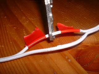
Also don't connect the camera to the 12V DC power plug until everything else is done. If things seem not to function directly disconnect the 12V DC power plug. Check the above before going on.
- Blackbox balun
The balun (Blackbox, and Code search for: IC441A) transforms the RJ45 video signal into a BNC video signal ('VIDEO PAIR 4'). A RCAtoBNC plug and short distance cable (male-male RCA) is used to connect to the cam1. - Cam1. FoV~42°
PAL color camera (NCK41CVP and 3.5 - 8 mm focal length [FoV~ 75° - 32°]). The short distance cable (male-male RCA) connects to the 'VIDEO' of the camera and the 12V DC power plug connects to '12V DC'.
- long distance cable
- cam2 This setup is somewhat different from cam1, because it is assumed not such long distance has to be handled. So normally RG59 cable is used:
- medium distance cable
This black cable with RCA tulip connectors goes between the cam2 and PC1 locations (upto 11 meter). This cable (RG59) is used to transport the video signal to the cam2. - medium power lead
This grey cable lead extends the existing lead of a 12VDC power supply.
- Cam2. FoV~11°
For testing: PAL color camera (NCK41CVP and 3.5 - 8 mm focal length [FoV~ 75° - 32°]). The short distance cable (male-male RCA) connects to the 'VIDEO' of the camera and the 12V DC power plug connects to '12V DC'. - the PC side:
- cam1
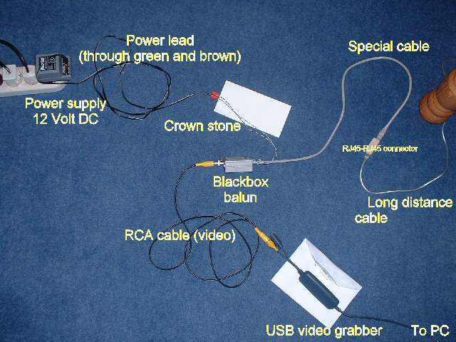
A short description of this setup:- long distance cable
this cable goes between the PC1 and cam1 locations (upto 600 meter). This cable (RJ45 Cat5 UTP) is used to transport the video signal and the power from the power supply. Only a short cable is provided by me.
- RJ45-RJ45 coupler
The connector connects the long distance cable to the special cable - Special cable
This cable splits the video signal and the power. The video signal ends up in the RJ45 connector (to the Blackbox balun), while the power goes to the two twisted pairs into a crown stone - Crown stone
This connects to the power lead towards the power supply. This power lead is the rest of the clipped away lead from the power supply (be sure that the plus and minus are connected to resp. brown and green lead, if in doubt phone me, it can damage the camera!), at the other end is the power supply. So have the labeled side to the green twisted pair through the crown stone and connect the other unlabeled lead to the brown twisted pair. - Power supply (not
provided by VR)
This plugs into the 240 V connector. The power lead is clipped halfway; the part with the 12V DC power plug (1.2 mm x 5.5 mm coax power plug, tip: positive) is used on the cam1 side.
- Blackbox balun
The balun transforms the RJ45 video signal into a BNC video signal ('VIDEO PAIR 4'). A small RCAtoBNC plug is provided, making it possible to use the short distance cable (a male-male RCA cable) towards Winnov card in PC1 (this is contrary to above picture; which is only used for testing the setup and get some experience) - Winnov card
The RCA tulip connection (VIDEO) will be used of the Winnov card in PC1
- long distance cable
- cam2
- medium distance cable
(~ 11m)
Coming from the cam2 (which needs a small RCAtoBNC plug) will connect into the Winnov card; after converting it with a RCA to 8pin DIN cable
- Winnov card
The MXC connection (8pin DIN) will be used of the Winnov card in PC1
- medium distance cable
(~ 11m)
Testing
Gradually get some familiarity with the set up:- don't clip the power lead yet, but plug it into the camera (be sure that the plus is in the center!)
- get this to work
- include the medium distance cable and medium power lead, like in cam2 setup
- get this to work
- include the two Blackbox baluns with short long distance cable (provided). This all still with power lead still directly into camera.
- get this to work.
- Replace the short long distance cable with the real long distance cable (not provided).
- get this to work
- clip the power lead and connect the ends to the two crown stones (watch for the coloring of the cables, see above for some help) and test again with short and real long distance cable.
- get this to work (this would mimic the situation as depicted in
the above pictures)
- Then role out in real life locations
Equipment list provided
The following has been send (total insurance value [RRP] around 1125
Euro
[excl. VAT]):- Pack 1
- Winnov Videum ISA card plus User's guide
- one RCA to S-Video coupler (this one can't be used, replaced by RCA to 8pin DIN cable)
- Pack 2 (in this pack, everything is connected up as in the above
pictures; if you connect the power
supply to the camera
and the USB video grabber to
the PC it should work;-)
- Belkin USB video grabber
- Howent NCK 41CVP camera with 3.5 - 8 mm focal length [FoV~ 75° - 32°]).
- two Blackbox baluns
- two special cables with crown stones (each ~30 cm)
- one short long distance cable (ethernet cable, ~2m)
- two short distance cable
(male-male RCA cable, ~1m)
- two RJ45-RJ45 coupler
- two RCAtoBNC plug
- Pack 3
- ~11m of RG59 medium distance cable and medium power lead
- Pack 4
- ISpy software (two differently named copies [like ispy1.exe and ispy2.exe] run at the same time on PC1)<>
- <>Pack 5 (brought during my Oct. 2005 visit) <>
- PCC-7HM color camera (for cam2) plus power supply (2.1 mm. x 5.5 mm coax power plug, tip: positive) and LS-250 [FoV~ 11°] lens
- 15 cm RCA to 8pin DIN cable
- a waterproof container has been made for cam2
- Provided by Emma and Dick
- PC1 installed with
Windows2000 with ISA-bus and 3 GByte disk
- ADSL Internet connectivity
- real long distance cable (Cat5 UTP for cam1)
- one waterproof container (for cam1).
- Pack 6 provided by Victor
- one PCC-7HM color camera (incl. power suppply for Cam1: 3.6 mm @ CCD of 1/3")
- JAVA program (made by David Bosschaert) to grab pictures from PC1 (in case no Internet connection available) and the web-server.
- Making video from the (above) individually grabbed pictures using JPGAvi.
- An FTP server of PC1 (Serv-U)